ESP32S3基于espidf移植I2C SSD1306/sh1106 WouoUIPage磁贴案例
ESP32S3基于espidf移植I2C SSD1306/sh1106 WouoUIPage磁贴案例
- 📍个人相关STM32移植内容《HAL/LL/STD STM32 U8g2库 +I2C SSD1306/sh1106 WouoUI磁贴案例》
🔖上面文章包含个人移植的串口控制的
WouoUIPage STM32 HAL库I2C DMA方式工程版本,本案例是基于此版本移植到esp32上的。有关WouoUIPage的相关改进内容,请查看上面的内容,本文不再做介绍。
- 📺以下是B站up主移植
stm32 WouoUI Page版的作品展示。
STM32 WouoUIPage版使用TestUI例子演示和简要的代码讲解
- WouoUI Page版:
https://github.com/Sheep118/WouoUI-PageVersion
WouoUI Page版是基于WouoUIU8g2库版本思路,模拟来的。WouoUI:https://github.com/RQNG/WouoUI- 🔖个人此项目移植,也是在以上视频up主的
WouoUI-PageVersion开源工程基础上移植和改进的。
- 🎉ESPIDF版本:
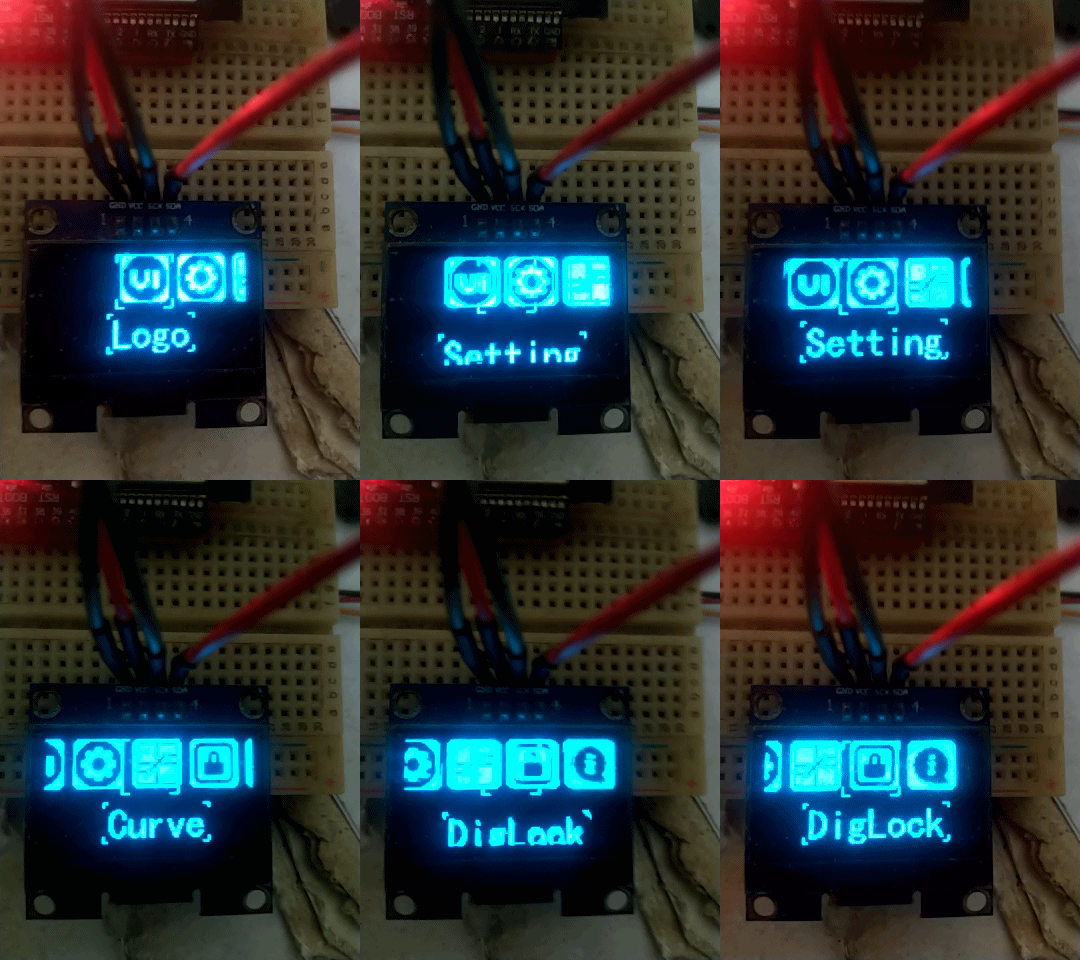
v5.4 - 🍁移植到esp32S3上的运行效果:


通过串口发送“abcd”中的任意一个字符,分别对应控制:确认、 上、下、返回。
- 🔧串口调试助手配置:(推荐使用:sscomV5131,ATK_XCOM)

- 如果想修改为其他控制方法,例如按键,可以修改代码,改为按键或者EC11编码器控制。只需注册对应的事件函数即可。本工程只是一个图形显示界面的菜单工程框架,可以很方便的移植到其他平台及MCU上运行。
- 📝main.c
#include <stdio.h>
#include <string.h>
#include <stdlib.h>
#include "freertos/FreeRTOS.h"
#include "freertos/task.h"
#include "driver/gpio.h"
#include "driver/rmt_tx.h"
#include "esp_system.h"
#include "esp_err.h"
#include "esp_log.h"
#include "led_strip.h"
#include "sdkconfig.h"
#include "driver/i2c_master.h"
#include "driver/uart.h"
#include "esp_lcd_panel_io.h"
#include "esp_lcd_panel_ops.h"
//#include "OLED.h"
#include "TestUI.h"#define CONFIG_BLINK_LED_STRIP_BACKEND_RMT  1#define BLINK_GPIO 48static const char *TAG = "WouoUIPage";static uint8_t s_led_state = 0;
static const char TARGET_CHARS[]="abcd";static led_strip_handle_t led_strip;#define UART_PORT UART_NUM_0       // 使用 UART0
#define BUF_SIZE 1024              // 接收缓冲区大小
#define BAUD_RATE 115200           // 波特率
#define TX_PIN GPIO_NUM_43         // UART0 的 TX 引脚
#define RX_PIN GPIO_NUM_44         // UART0 的 RX 引脚static void blink_led(void)
{/* If the addressable LED is enabled */if (s_led_state){/* Set the LED pixel using RGB from 0 (0%) to 255 (100%) for each color */led_strip_set_pixel(led_strip, 0, 50, 0, 0);/* Refresh the strip to send data */led_strip_refresh(led_strip);}else{/* Set all LED off to clear all pixels */led_strip_clear(led_strip);}
}static void configure_led(void)
{ESP_LOGI(TAG, "Example configured to blink addressable LED!");/* LED strip initialization with the GPIO and pixels number*/led_strip_config_t strip_config = {.strip_gpio_num = BLINK_GPIO,.max_leds = 1, // at least one LED on board};
#if CONFIG_BLINK_LED_STRIP_BACKEND_RMTled_strip_rmt_config_t rmt_config = {.resolution_hz = 10 * 1000 * 1000, // 10MHz.flags.with_dma = false,};ESP_ERROR_CHECK(led_strip_new_rmt_device(&strip_config, &rmt_config, &led_strip));#endif/* Set all LED off to clear all pixels */led_strip_clear(led_strip);
}// 任务2:每1s运行一次
void task_1s(void *pvParameters) {while (1) {// ESP_LOGI("TASK_1S", "1s task is running");blink_led();/* Toggle the LED state */s_led_state = !s_led_state;vTaskDelay(pdMS_TO_TICKS(1000)); // 延迟1s}
}void uart_init() {uart_config_t uart_config = {.baud_rate = 115200,.data_bits = UART_DATA_8_BITS,.parity = UART_PARITY_DISABLE,.stop_bits = UART_STOP_BITS_1,.flow_ctrl = UART_HW_FLOWCTRL_DISABLE,.source_clk = UART_SCLK_DEFAULT,};uart_driver_install(UART_PORT, BUF_SIZE * 2, 0, 0, NULL, 0);uart_param_config(UART_PORT, &uart_config);uart_set_pin(UART_PORT, GPIO_NUM_43, GPIO_NUM_44, UART_PIN_NO_CHANGE, UART_PIN_NO_CHANGE);
}
//接收回调
void uart_receive_task(void *pvParameters) {uint8_t *data = (uint8_t *) malloc(BUF_SIZE);while (1) {int len = uart_read_bytes(UART_PORT, data, BUF_SIZE, 20 / portTICK_PERIOD_MS);if (len > 0) {// 检查是否包含目标字符for (int i = 0; i < len; i++) {if (strchr(TARGET_CHARS, data[i]) != NULL) {ESP_LOGI("UART", "Received target character: %c", data[i]);// 在这里添加处理逻辑switch(data[i]) { //没有按键,使用串口代替case 'a':OLED_MsgQueSend(msg_click);break; //单击case 'b':OLED_MsgQueSend(msg_up);break; //上翻页case 'c':OLED_MsgQueSend(msg_down);break; //下翻页case 'd':OLED_MsgQueSend(msg_return);break; //返回default:break;}}}}}free(data);vTaskDelete(NULL);
}void app_main(void)
{// 初始化 UARTuart_init();configure_led();ESP_LOGI(TAG, "Initialize I2C bus");TestUI_Init();OLED_operate_gram(PEN_CLEAR);//清缓存
// 创建任务接收 UART 数据xTaskCreate(uart_receive_task, "uart_receive_task", 4096, NULL, 1, NULL);// 创建任务2:1s调度xTaskCreate(task_1s, "Task_1s", 2048, NULL, 1, NULL);while (1){TestUI_Proc();}}
📚工程源码
通过网盘分享的文件:I2C_SSD1306_OLED_WouoUIPage.rar
链接: https://pan.baidu.com/s/1H9E8PP9zu2A2wQfVJNoT3w?pwd=ayq5 提取码: ayq5
